Parametric Design Workflow: From Parameters to Fabrication
Parametric design is not a name for every curved building, nor is it synonymous with a futuristic visual style. It is a way of constructing a model in which variables and their relationships are explicit. If an opening width, solar angle or façade spacing changes, the effect travels through defined rules instead of requiring every part to be redrawn. Its value therefore lies in the logic of dependencies and the ability to test them, not in the novelty of the resulting form.
The method may produce a free-form roof, but it can just as readily produce a rectilinear grid, an area schedule or the numbering of repeated components. A sound model does not replace architectural judgement. It exposes assumptions and makes visible where calculation ends and professional judgement begins. This article follows the process from framing the question to coordination and fabrication, using two cases to distinguish controlled geometric change from performance claims that still require measurement.
What makes a model parametric?
A parametric model begins with definable inputs: site dimensions, orientations, levels, unit counts, permitted span ranges, thicknesses or angles. Explicit relationships then connect them. An element may follow an axis, division points may derive from a path length, and an opening may be calculated from a stated ratio. The output is not detached from these relationships; it is one state within a system that can be updated.
A numerical field in modelling software is not sufficient by itself. If inputs lack a clear logic, or the result needs manual repair whenever a number changes, the model is brittle. Conversely, a parametric system can produce extremely simple geometry when its dependencies are traceable. Continuity between question, input, relationship and output is the more reliable test.
Parametric, computational, generative and BIM are not synonyms
Computational design is the broader field: an algorithm or procedure transforms data into a result. A parametric model foregrounds editable variables and the dependencies that update that result. A BIM model may contain extensive parameters for type, material and quantity without generating a building’s form. Equally, a curved surface can be drawn digitally without a relationship system suitable for exploration.
Generative design produces a family of alternatives from rules, after which selection still needs criteria. Computational optimisation adds declared objectives and constraints—for example, reducing façade area within daylight, span and cost limits. The “best” result is not neutral; it is best under the objectives, weights and data chosen by the team. Parametricism, meanwhile, is a particular design discourse associated with Patrik Schumacher and should not be used as a synonym for every parametric model.
From a design question to an auditable graph
We start with a bounded question that can be tested. How can a target shading ratio be maintained as façade orientation changes? What span range is possible before the structural depth changes? How can units be distributed while preserving circulation and setbacks? Constants are then separated from variables, units, ranges and constraints are declared, and relationships are built incrementally. Each stage is tested before more complexity is introduced.
In visual programming environments, data passes through nodes and connections from inputs to operations and outputs. The legibility of that route matters more than the number of nodes. Every input needs a name, unit, source and owner; every output needs a purpose, whether it supports a design decision, structural coordination, quantity take-off or fabrication. If the team cannot explain a relationship or run it again against another data set, the graph is not yet a dependable professional asset.
The British Museum Great Court: controlled difference, not randomness
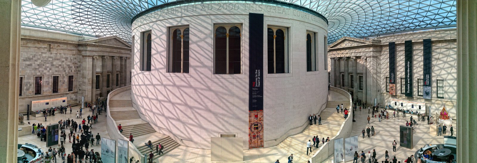
The British Museum Great Court roof makes controlled variation legible. It spans an irregular courtyard around the circular Reading Room and contains 3,312 individual glass panels, no two of the same shape. The significance is not the number alone. A complex surface was translated into discrete elements that could be calculated, described, fabricated and assembled as one coordinated system.
Geometry and data are directly connected. A change in node position or surface boundary affects the families of steel members and panels, then propagates to identification, detailing and manufacture. Treating the roof only as a free-form image would lose that chain of coordination. The example shows that the project’s real body of work is not just its final silhouette, but the relationship between the model, component register, interfaces and revisions.
Al Bahr Towers: a moving form does not prove performance by itself
At Al Bahr Towers in Abu Dhabi, external shading units respond to the sun, opening and closing as its position changes. The project architect states that the screen was designed to reduce solar gain by up to 50 per cent. Here parameters do more than describe geometry: orientation, time and component state are connected through an operational control logic.
A moving façade does not, however, make every environmental claim true automatically. The geometric output has to be distinguished from thermal simulation, and the weather file, glazing assumptions, operating hours, failure states and measurement method have to be documented. The same rigour is needed when critiquing modern Saudi architecture: identity and comfort cannot be inferred from a façade image, but from a defined decision and an effect that can be examined.
From geometry to fabrication: where precision becomes responsibility
Before a model reaches fabrication, relationships have to become part families, tolerance limits, fixing interfaces and an assembly sequence. Reducing the number of types may lower complexity, but it may also alter form or performance. Increasing uniqueness may be digitally possible while raising the risks of tracking, installation and replacement. The decision requires a comparison between the value of variation and the cost of producing, inspecting and maintaining it.
Every component needs a stable identifier. Units and coordinate systems must agree across architect, engineer and fabricator, and a sample of outputs should be checked outside the tool that produced them. The model version from which a fabrication file was issued also has to be fixed. Without that trail, regenerating geometry becomes hazardous: a new file may look correct while part numbers or fixing points have changed.
How parametric models fail
A model fails when variables accumulate without serving a decision, important assumptions disappear inside a component that only its author can read, or relationships break at ranges that were never tested. Decimal output can create false precision when site or material data is approximate. The model also fails when it produces hundreds of options without an exclusion criterion, turning exploration into a visual burden rather than knowledge.
Geometry is not the whole programme. Our reading of mosque architecture elements shows that movement, sound, qibla and climate cannot be reduced to a pattern. Geometric ornament in Islamic architecture may follow historical systems of proportion and repetition, but that does not automatically make it a contemporary digital parametric model.
Governing the model as a team
We treat the model as a shared, auditable document. We record the question it was built to answer, the inputs and their units and sources, the constraints that must not be crossed, the owner of each decision, and the outputs on which others depend. Test cases are added at minimum and maximum values, a sample is checked independently, and a clear point is set at which exploration stops and controlled issue begins.
This governance turns parametric design into team knowledge rather than a skill locked inside an opaque file. The method is strongest when it preserves the reason for a decision, shows the consequence of change, connects an option to an explicit criterion, and carries geometry into coordinated and manufacturable information. A distinctive form is one possible result, not the definition.