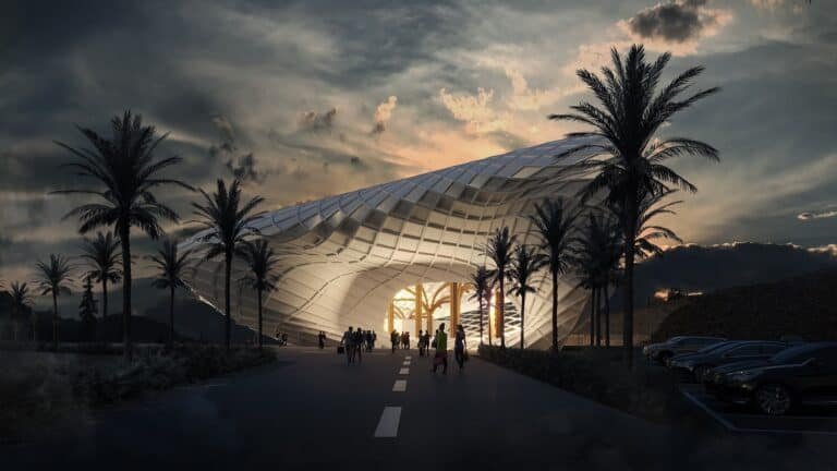
MOSS: Storing Oil on Water — When the Hormuz Crisis Became an Architectural Question
The idea for MOSS did not begin as an attempt to design a new tank. It began by observing a crisis that goes beyond the shape of the tank itself. In spring 2026, as tensions in the Gulf escalated and shipping through the Strait of Hormuz was disrupted from early March, many architects and engineers found themselves preoccupied with a single question: can conventional energy infrastructure respond to a sudden crisis? At INJ Architects we were among those who thought long about it, and we emerged with a design study that we present here in full: MOSS — Modular Offshore Storage System.
We publish this research because we have decided that our studies should not stay in drawers. Architecture, for us, is not only the design of buildings but a way of thinking about systems, materials and environments. MOSS is an example of that: an industrial design output rather than an architectural one in the narrow sense, yet it carries our entire architectural method of reading a problem and turning it into form, material and assembly.
1. Origin: When Oil Storage Became an Architectural Question
The problem is not only extracting oil, but the capacity to store it, move it and redistribute its reserves when supply chains fail or existing facilities become exposed. The Strait of Hormuz is one of the world’s most important maritime energy corridors; according to the International Energy Agency, roughly 20 million barrels per day of crude and petroleum products passed through it in 2025, close to a quarter of globally seaborne oil trade.
Data published by the US Energy Information Administration in November 2026 shows the scale of the disruption: flows fell from 21.6 million barrels per day in the fourth quarter of 2025 to just 5.1 million barrels per day in the second quarter of 2026, recovering to 9.1 million in the third quarter. These figures expose the fragility of relying on a handful of chokepoints. To be precise, however, they do not mean that the storage system we propose could solve the strait’s crisis or replace those volumes.
The research idea grew from an entirely different question: what if oil storage could be transformed from a fixed, massive facility into a set of small, independent units that can be transported, assembled and expanded on the surface of the water? From there began an inquiry into the relationship between architecture and industrial infrastructure, and how modular design principles from buildings and products might be transferred to offshore storage systems.
2. The Research Question: Modularity, Flexibility, Buoyancy
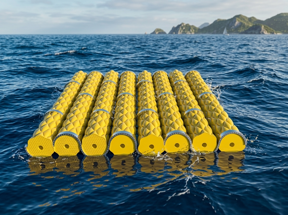
MOSS proposes exploring an offshore storage system built on three principles: Modularity — Flexibility — Buoyancy. Instead of one large, centralised depot, the depot is made of separate units that can be connected to one another, so that capacity becomes scalable up or down according to need.
The fundamental shift in thinking is that the project treats water as a medium that carries the system, not merely a structural obstacle to be overcome. The question changes from designing rigid walls to resist a liquid into researching flexible envelopes capable of containing it, supported by a connection and anchoring system that allows relative movement. Let us say it clearly from the outset: the project does not yet offer a finished industrial product or a certified facility, but a design study investigating the potential of this shift.
3. Comparison with Conventional Oil Storage
The oil industry relies on a familiar set of systems: onshore tanks of steel or concrete with large capacities, requiring specific sites, foundations and operational and safety systems; underground storage in salt caverns and geological formations dedicated to strategic reserves; offshore storage via tankers or floating storage and production units (FSO and FPSO); and flexible storage in fabric tanks or foldable industrial envelopes used in particular applications, including temporary storage of fuel and recovered oil.
MOSS does not claim that flexible floating storage is unprecedented. It proposes studying a different configuration of it, based on long cylindrical units repeated within an interconnected matrix. The proposed difference is that the depot is not designed as a single body but built from units that can be separated, assembled and changed.
4. Why Store Oil on Water?
The global ocean covers about 71% of the Earth’s surface. That figure became a starting point for thinking about water bodies as a carrying structure for transportable facilities, instead of dedicating land to every new storage need. The project does not assume, however, that all marine surfaces are available or suitable; that depends on ecosystems, depth, shipping traffic, use permits, mooring locations and the nature of waves and currents.
The aim is to study the possibility of creating additional temporary reserves in suitable marine locations, especially near ports, industrial facilities and logistics support areas. Architecturally, MOSS treats water as part of the structural system, where buoyancy performs the load-bearing role that foundations perform in buildings.
5. Composition of the Basic Unit
After several formal experiments, the concept settled on a long cylindrical unit resembling a battery or an industrial bag filled with liquid. Early studies explored polyhedral frames and geometric structures close to crystals or ice moulds, but these evolved toward a simpler configuration more closely tied to assembly and manufacture.
| Property | Preliminary Design Value |
|---|---|
| Unit length | approx. 10 m |
| Outer diameter | approx. 1 m |
| Proposed central void | approx. 25 cm |
| Length-to-diameter ratio | 10:1 |
| Units per assembly | 20–30 |
| Deployment orientation | Horizontal on the water surface |
| Envelope | Flexible and reinforced |
| Connection system | Aluminium rings and flexible joints |
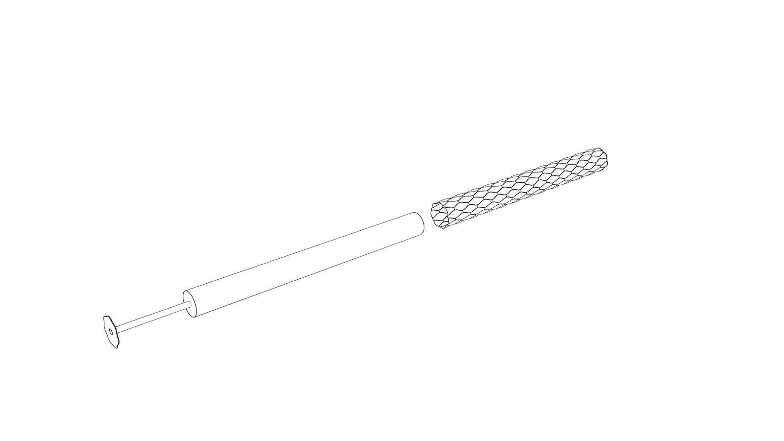
The body consists of a closed flexible envelope that can be filled and emptied through ports fitted with valves and hose connections. The goal is for the body to keep a taut, inflated appearance when full, without becoming a conventional rigid cylinder. The central void is part of the formal and operational thinking: its use for routing connections or controlling water and air was discussed, and defining its final function requires a detailed sectional design.
6. The Battery Idea and Modular Assembly
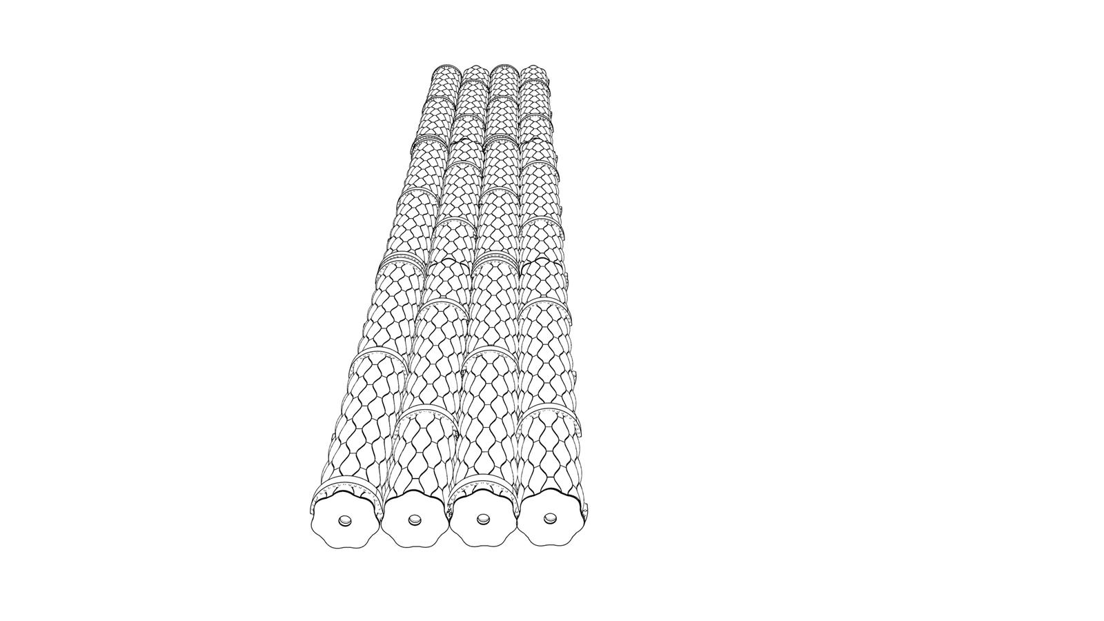
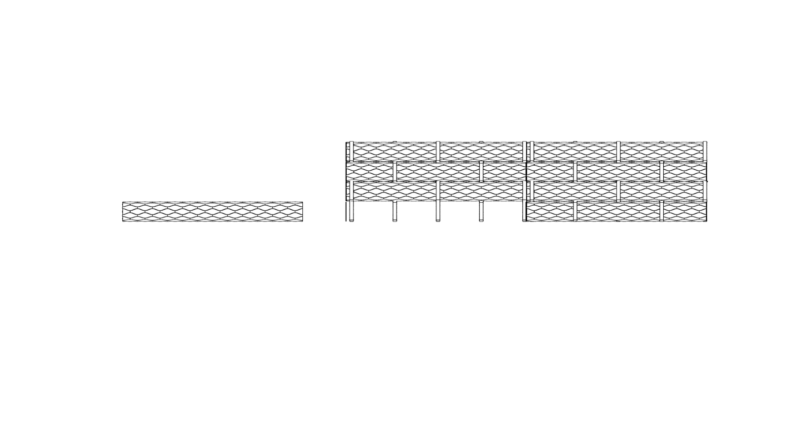
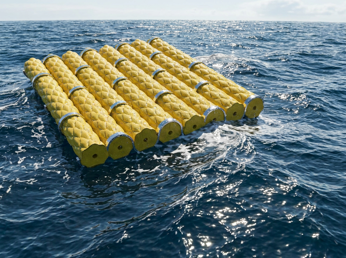
The core visual idea rests on a simple principle: imagine long batteries placed side by side, joined by light metal pieces, with more batteries added to the group whenever needed. Units can be arranged in parallel rows or regular groups to form a floating storage field.
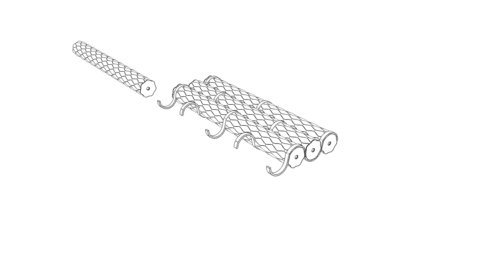
The depot need not be manufactured in one place; units are assumed to be fabricated separately, transported and assembled at the marine site, with logistical and construction details still under study. The value of this configuration lies in three things: incremental expansion, replacement of an individual unit, and rearrangement of groups as needs change.
Hence the wish to develop extremely simple assembly diagrams, close to the visual language of furniture assembly catalogues: a reader should understand how the system goes together from a clear exploded diagram, without complex engineering explanation.
7. Rings and Joints
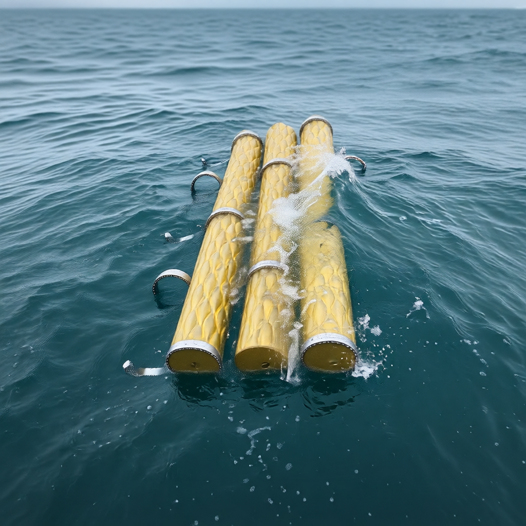
In the early models the rings around the units appeared as conventional metal elements. The concept later evolved toward segmented rings acting as flexible connectors rather than fully rigid collars. The aim is to keep the units in order and prevent uncontrolled separation, while allowing limited relative movement as waves pass.
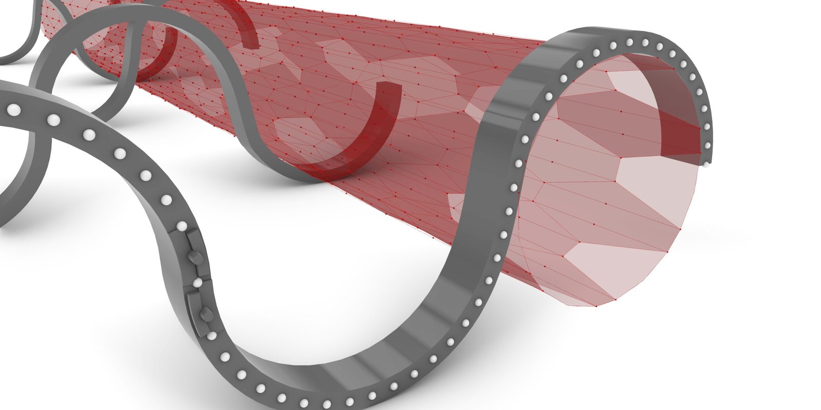
The design favours marine-grade aluminium or elements with suitable corrosion resistance over the look of heavy iron, with hinged or flexible connections between parts. The idea requires studying how loads distribute at the envelope’s connection points, so that the rings do not become stress concentrations or friction points that damage the material. The rings that hold the units’ form should also be kept separate from the mooring system that fixes the group in place.
8. Material: From Flexible Water Tank to Marine Composite Envelope
Material exploration began with flexible water tanks known as Flexible Pillow Tanks, made of PVC-coated synthetic fabric. Published specifications for products of this kind indicate fabrics weighing around 1000–1100 g/m², declared tensile strength between 2600 and 2800 N per 5 cm depending on weave direction, and a temperature range of −30 to +70 °C. These products demonstrate that large foldable tanks can be manufactured from reinforced fabric with heat-welded layers.
But drinking-water tank material cannot automatically be adopted for crude oil. The oil version needs a specialised envelope compatible with the hydrocarbon type, temperature and operating conditions, with testing for permeability, corrosion, fatigue and delamination. Research alternatives include fabrics reinforced with fuel-resistant polymer layers, such as certain polyurethane formulations used industrially in flexible fuel tanks. Existing commercial floating oil storage products have shown that oil-resistant fabrics can be combined with marine aluminium fittings within the scope of temporary storage.
9. The Parametric Skin
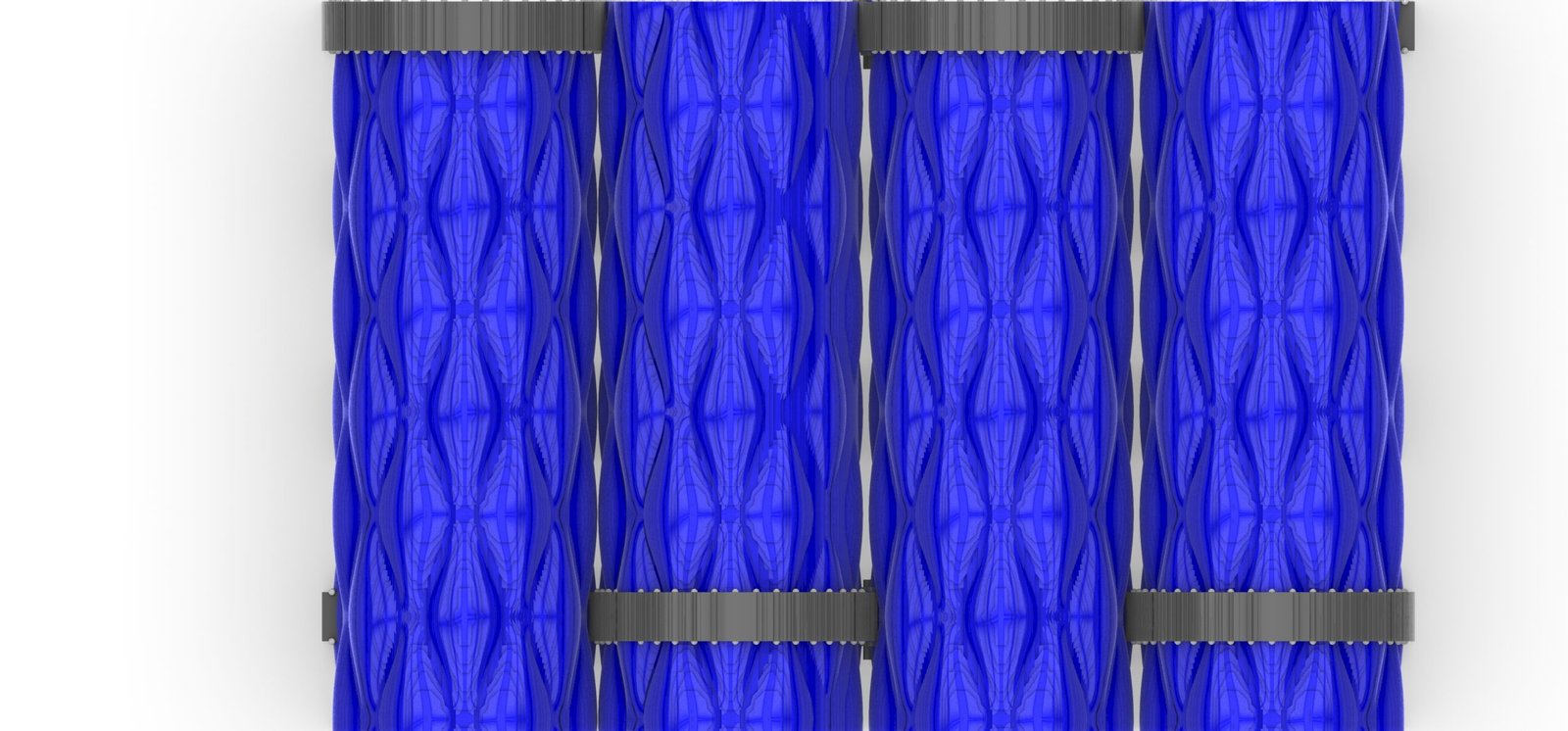
The design of the outer envelope is the part of the project most closely tied to architectural research. The intent was never a fully smooth cylindrical surface, but a skin with regular repeating undulations that reveal the material’s flexibility and its behaviour under tension. One visual reference came from the Tower of Light in Manchester and its Shell Lace system, which uses curved-surface geometry and incisions to generate structural performance. MOSS does not transfer the tower’s system literally — the tower is a rigid metal shell while MOSS works with a flexible membrane — the lesson concerns the principle of linking geometry to performance.
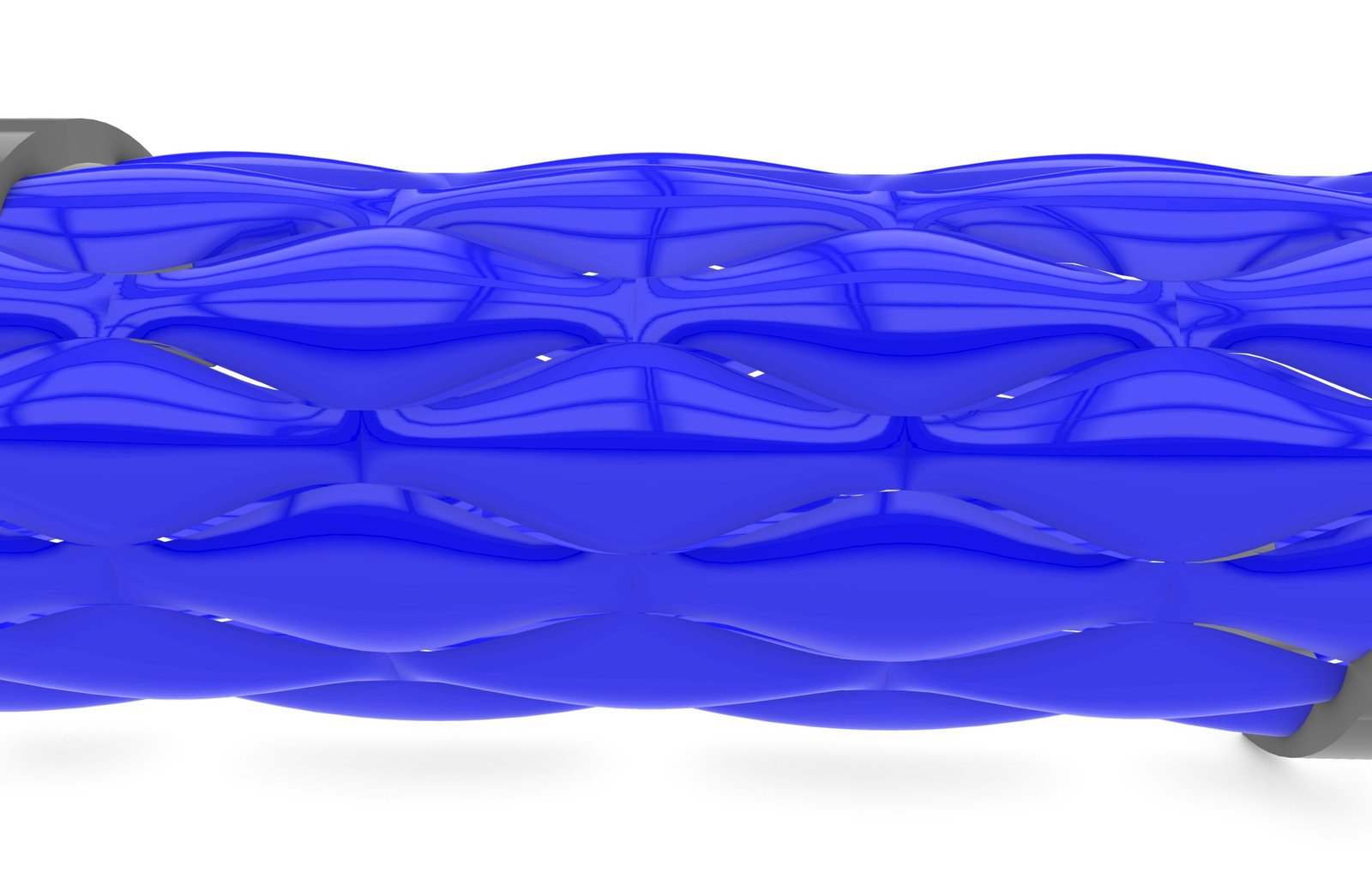
In the drawings the idea evolved toward a surface resembling stretched skin, with light geometric bulges and creases, rather than a large external net of ropes. The first conception included crossing helical ropes around the body; the direction then settled on a lighter tension system, integrated or hidden within the envelope, so that the effects of tension show on the surface without ropes dominating the image.
The design hypothesis is that surface geometry and integrated reinforcement may help control deformation during filling and emptying. Scientifically, let us be frank: no tests yet prove that the chosen pattern reduces stress or raises pressure resistance, and this must be demonstrated through structural analysis and material testing before the function is adopted.
10. Physics: Oil and Water
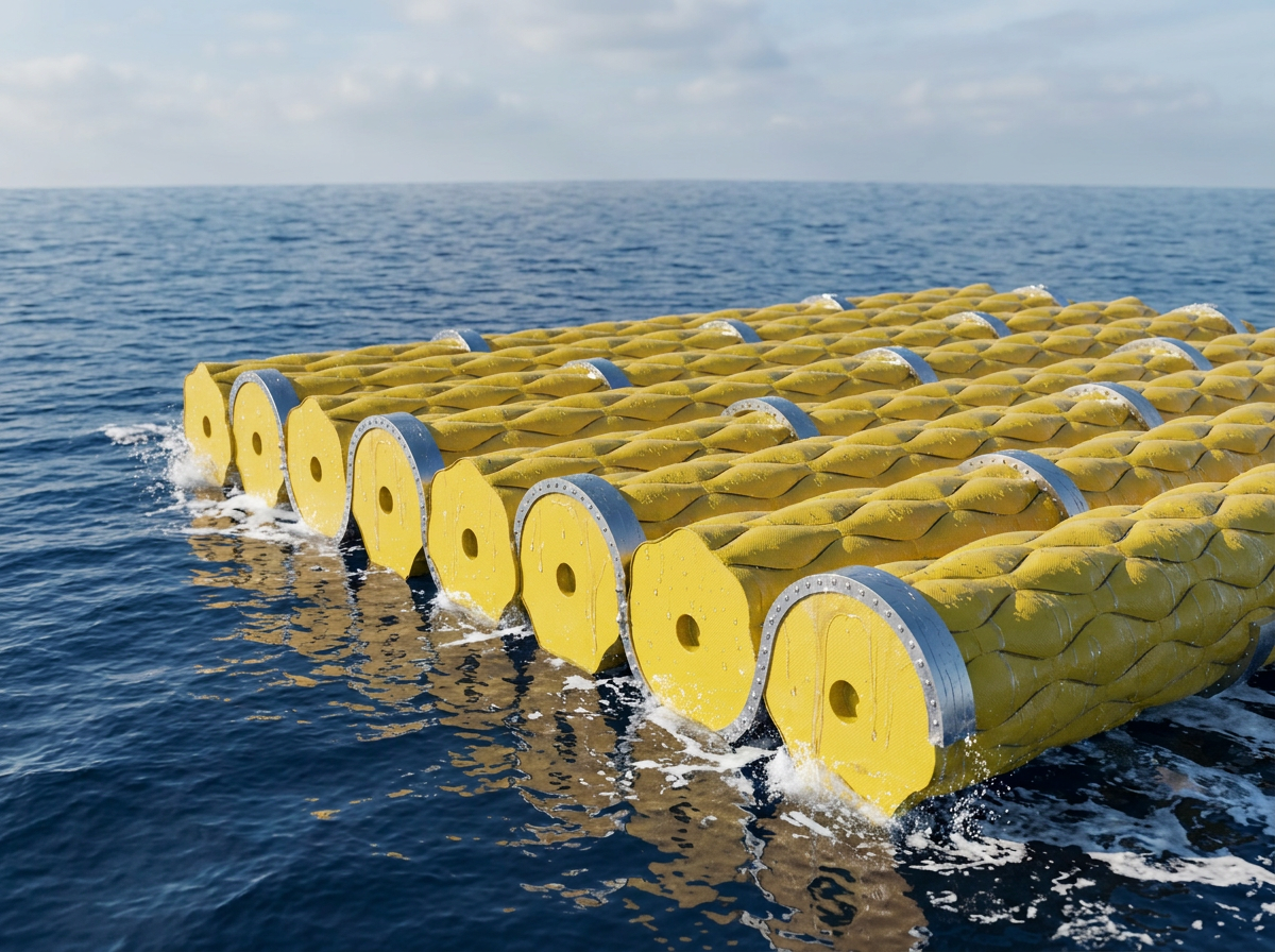
Buoyancy rests on Archimedes’ principle. Most crude oils are less dense than seawater, though density varies with the crude, temperature and composition. For a preliminary study, a nominal density of 850 kg/m³ for oil against roughly 1025 kg/m³ for seawater can be assumed. For a sealed body containing oil, buoyancy depends on the volume of water displaced against the weight of the liquid, envelope and fittings.
Neglecting the weight of the envelope, fittings and any air chambers, these densities give a theoretical submersion of about 83% of displaced volume. A full oil unit will therefore not ride high above the sea like an air float; most of its volume will be submerged. This behaviour can be adjusted with additional buoyancy elements or sealed air chambers, which require separate calculation. Horizontal orientation, moreover, is not guaranteed by density alone; stability is determined by body shape, centres of mass and buoyancy and connection points, and must be proven across fill states and under wave action.
11. Envelope Behaviour During Filling and Emptying
Each unit is assumed to pass through three operating states. State one (Empty / Underfilled): the envelope is slacker and may show folds from low content; the system needs a way to hold the unit’s shape and stability. State two (Partially Filled): the envelope’s form changes as the liquid level rises and the material responds to varying tensions; this state needs particular study for possible changes in stability and internal liquid movement. State three (Filled): the envelope becomes taut and the skin geometry reads clearly, though the unit’s safety must rest not on its inflated appearance but on permitted pressure limits, weld strength and the valve system.
The parametric pattern does not automatically relieve hydrostatic pressure; its potential role is to influence how deformation occurs and how forces travel through the membrane. No physical laboratory experiment has yet been carried out within this project to prove filling and emptying behaviour or the envelope’s ability to recover its shape.
12. The Central Void and the Fluid System
The unit was first conceived with an annular section, close to a doughnut but elongated. Dedicating the inner space to water or air was discussed as a possible means of helping to control buoyancy and weight, or of providing a passage for some operating elements. The design must resolve the difference between the central passage and the liquid inlet to the storage chamber: an axial passage open to the sea may fill with seawater and fail to act as a buoyancy chamber, while a sealed air chamber requires separate closure and monitoring.
Conceptually, the proposed operating system includes a filling port, a discharge port or multifunction connection, isolation and control valves, and means of monitoring pressure and leakage. The principle is that each unit can be isolated and maintained without emptying the whole group.
13. Waves and Marine Motion
One aim of the project is to let the group move with the waves without losing cohesion, which is why the design moved from a heavy external frame to a system of rings, flexible hinges and movable links. Units are expected to respond to sea motion in a limited way, while the connections absorb part of the relative movement.
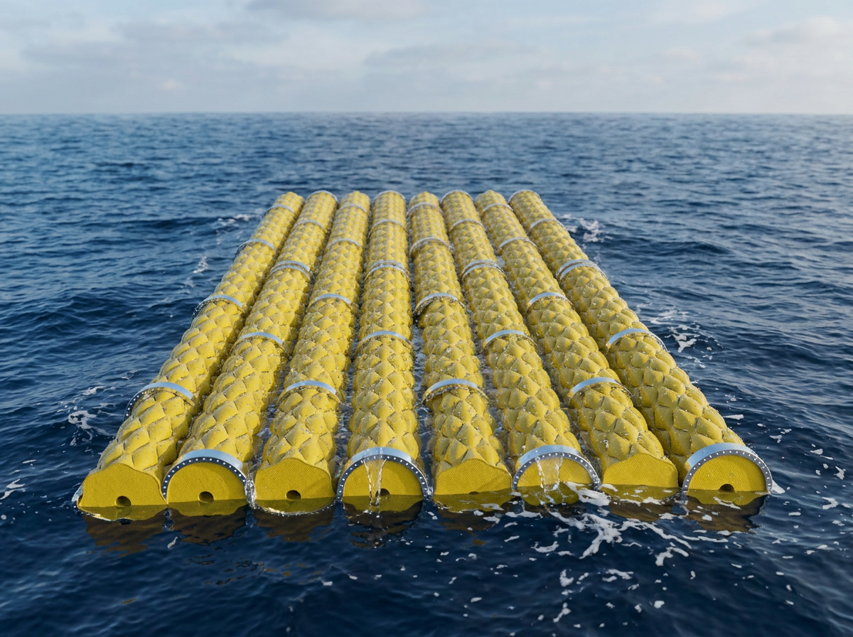
Flexibility does not necessarily mean lower loads, and repeated motion may fatigue the envelope or the connections. The study needs calculation of wave, current and wind loads, connection and mooring forces, collision between units, and system behaviour in storms. Testing is assumed to begin in a relatively sheltered marine area rather than assuming direct deployment anywhere in the open sea.
14. Isolation, Safety and Risk Distribution
Splitting storage capacity into independent units is one of MOSS’s core motivations. Instead of holding the whole quantity in one chamber, it is distributed across separate chambers, each with its own ports and isolation elements. In theory this can limit the quantity of liquid exposed to leakage in some local failure cases, especially when units are isolated from one another by closed valves.
This does not make the system automatically safe; a leak from a single unit could cause serious marine pollution, and waves, collision or connection failure could cause simultaneous damage. The modular configuration should therefore be regarded as a proposed strategy for distributing risk, not a substitute for leak prevention, secondary containment and emergency response. Development requirements include double-wall study, leak detection, rapid isolation, impact protection, fire resistance and procedures for withdrawing damaged units.
15. The Nearest Application: Temporary Storage — and an Extension Toward Oil Recovery from Water
The project began from a question about strategic storage, but the proposed unit dimensions currently point to an application closer to temporary or supporting storage. A group of 20 to 30 small units cannot be considered a direct substitute for national strategic reserves measured in millions of barrels. More specialised uses can nevertheless be studied: logistical support near offshore facilities, temporary capacity near ports, or certain emergency storage cases once safety is proven. Such applications benefit from units that can be assembled, replaced or removed without a permanent onshore storage facility.
There is another direction we consider promising, arising from the same physical principle: oil floats. The logic that lets a flexible unit carry oil on water also qualifies it for a role in recovering oil from the water surface during spill response, as floating temporary containers for what is skimmed from the surface, which can be assembled, towed and emptied by the same modular logic. This is a proposed extension the research opens rather than a proven result, but it shows how one design question can serve two ends: securing reserves and protecting the sea.
An economic comparison with onshore tanks and existing marine systems remains necessary before claiming the solution is faster or cheaper.
16. Estimated Storage Capacity
Treating the unit as a regular cylinder 10 m long with a 1 m outer diameter and a through central passage 25 cm in diameter, the theoretical liquid volume follows from the annular cross-section:
| Measure | Theoretical Volume or Capacity |
|---|---|
| One unit | 7.36 m³ ≈ 7,363 litres ≈ 46.3 barrels |
| 20 units | 147 m³ — about 926 barrels |
| 30 units | 221 m³ — about 1,390 barrels |
These are preliminary engineering figures, not certified operating capacities. Actual capacity may fall due to envelope deformation, unit ends, requirements against complete filling, component thickness and compensation systems. They show that the current version is closer to a small storage network or an expandable prototype than to a large strategic offshore depot.
17. Formal Evolution of the Project
The design passed through six clear stages. One — Frame and Bladder: a geometric external frame holding a flexible bladder, studied in cubic, octahedral and polyhedral forms and then irregular crystalline ones. Two — Cylindrical Modular System: the polyhedral configuration replaced by long cylindrical units with a central void, laid side by side, where the battery idea emerged as the visual reference. Three — Rings and Flexible Connections: metal rings added, then developed into segmented joints allowing movement.
Four — Parametric Skin: the undulating envelope, moving from visible ropes to a lighter tension system and a skin-like reading of the surface. Five — Floating Field: the single unit became a system of 20–30 units or more, with a conception of how they connect on the water. Six — Visualization and Research Communication: 3D models, assembly boards and marine renders in a unified visual language, so the project reads as a research system rather than a set of separate images.
18. Visual Identity
The visual direction settled on a clean, clear industrial language. Units appear in a high-visibility colour above the sea, with yellow or orange preferred for contrast against blue water. The envelope is not transparent and should never look empty or slack in images of the full state; the flexible skin should read taut, with clear repeating undulations. Rings and connections read as light aluminium rather than dark heavy metal. The sea is a real background with a logical submersion level, reflections and natural light, without exaggerated haze or cinematic effects.
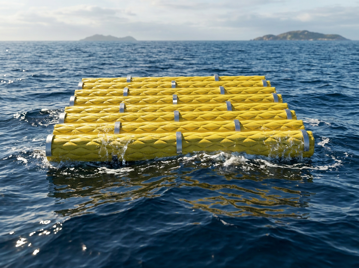
The visual requirements included a hero image of the complete floating group, close-ups of envelope and ring details, the unit plan and section, an exploded assembly diagram, a repetition diagram up to 20–30 pieces, and diagrams of fill states and motion. Modelling and rendering specialists worked under the supervision of the INJ Architects team, with a consistent instruction to unify background, lighting, colour and display scale, and a preference for clean diagrams close to industrial assembly catalogues over crowded scenic drawings.
19. Originality and Prior Research
MOSS’s originality calls for careful reading, and we prefer accuracy to assertion. Prior technologies and research already exist for storing oil in flexible envelopes above and below the sea surface, including commercial floating flexible oil storage products and engineering studies of modular offshore oil tanks and mooring systems. A 2026 study titled Discussion on the Concept and Key Technologies of Flexible Oil Storage in Waters examined flexible composite envelopes and water bodies, pointing to challenges of leakage, pressure, maintenance and environmental loads, and noting that the field still needs development and testing.
MOSS should therefore not be presented as the invention of the first flexible floating oil tank. The proposed contribution centres on the specific configuration of the cored cylindrical unit, its arrangement as a repeating group, the hinged connection system, the geometrically patterned envelope, and the logic of assembly and expansion. These elements themselves require detailed comparison with prior technologies and patents before any legal or research judgement on novelty.
20. Risks and Open Engineering Questions
Fundamental matters remain to be addressed before moving from concept to an operating prototype:
- Material: identifying a composite suitable for crude oil, and testing hydrocarbon resistance, permeability, welds and service life.
- Buoyancy and stability: calculating submersion, orientation and centres of mass and buoyancy in partial and full fill states.
- Parametric envelope: testing the pattern’s effect on deformation, stress and fatigue rather than assuming its effectiveness.
- Joints and mooring: determining forces transferred between units and designing connections that withstand sea motion without damaging envelopes.
- Environmental safety: developing leak prevention, containment and detection, and verifying requirements of the competent maritime authorities.
- Operation: designing valves, pumps, hoses and procedures for filling, emptying, isolation and maintenance.
- Economic feasibility: comparing manufacturing, transport, assembly, operating and maintenance costs with existing solutions.
It is important not to claim these matters are settled merely because the modelling or rendering succeeded.
21. Proposed Research Programme
MOSS can be developed in linked stages: beginning with documentation of the design logic, references, images, sections and assemblies; then computational models for buoyancy, stability and capacity, followed by a preliminary study of envelope, tension and connections; then a scaled sample manufactured with a non-hazardous liquid to test form, buoyancy and envelope response, without jumping straight to an oil trial; and once measurable results exist, moving to specialised industrial testing with marine engineers, materials laboratories and safety authorities. These stages remain proposed, not completed, work.
22. MOSS within INJ Architects and Intellectual Property
The project is a study led by architect Ibrahim Nawaf Joharji within the research activity of INJ Architects, extending our conviction that architectural practice is not confined to designing buildings but includes research into systems, materials, environments and how they are organised. Its value to the practice lies in demonstrating a design methodology: how to move from an infrastructure crisis to a formal, material and operational study.
The intellectual property of this research is reserved in full to the INJ Architects team. We publish it in keeping with our commitment that our research should not remain in drawers, for the wider benefit and to make our way of working clear. The research work is attributed to its authors, and its current classification remains research modelling and visualisation.
23. Closing Statement
MOSS is not an attempt to design yet another conventional oil tank. It is research into the possibility of redefining storage as a system capable of growth, disassembly and reconfiguration. The project starts from a crisis of infrastructure rigidity in the face of energy disruption, then seeks a design response based on small units instead of a single mass, buoyancy instead of ground foundations, and flexible envelopes instead of rigid walls.
The idea still needs engineering, environmental and economic proof, but that does not negate its research subject. The question it poses is not only how liquid can be stored at sea, but how storage itself can be organised as an adaptive architectural and industrial system.
MOSS — From Fixed Storage to Adaptive Floating Infrastructure.
Fact Sheet
| Name | Modular Offshore Storage System (MOSS) |
| Principal researcher | Ibrahim Nawaf Joharji — INJ Architects |
| Driver | Energy disruption and offshore storage security; Strait of Hormuz crisis — spring 2026 |
| Proposed unit | 10 m long × 1 m diameter, central void ≈ 0.25 m, ratio 10:1 |
| Target unit count | 20–30 |
| Theoretical capacity | 7.36 m³ per unit; 147–221 m³ per group |
| Storage type | Floating, flexible, modular |
| Connections | Marine aluminium rings and joints |
| Skin | Parametric / patterned membrane |
| Study type | Conceptual architectural and industrial research |
| Physical testing | Not yet carried out |
| Nearest application | Temporary or supporting storage, and oil recovery from water — under study |
| Intellectual property | Reserved to the INJ Architects team |
References
- International Energy Agency — Strait of Hormuz
- US Energy Information Administration — Global Energy Security Data, November 2026
- IEA — Oil Security and Emergency Response
- Lamor — Floating Oil Storage Tanks
- Hou & Mei (2026) — Flexible Oil Storage in Waters
- Modular Floating Oil Tanks and Mooring Research — Ocean Engineering
- Tonkin Liu — Tower of Light / Shell Lace Structure
- NOAA — The Ocean · IMO — MARPOL Convention
All images and drawings are from the INJ Architects archive. Copyright and intellectual property reserved © INJ Architects. This document is a research reference file, not a certified feasibility report nor a certificate of operational performance.